
- 1- Basics of phytosanitary treatments
- 2- Spraying equipment
- 3- Machine elements
- 4- Maintenance
- 5- How to calibrate the airblast sprayer
The objective of a phytosanitary treatment is to distribute a pesticide in an efficient and friendly manner respect to the operator and the environment. To achieve this, the treatment must:
- be carried out in a safe way for the operator
- adequately control the pest, influencing the auxiliary fauna and the rest of the ecosystem as little as possible
- leave as little residue as possible on the fruit that could affect human health
- be economically profitable
Most of the phytosanitary treatments are applied by spraying or dusting. Spraying consists of the fractionation of the mixture into drops, which is normally a plant protection product mixed with a liquid (usually water) and is then distributed over all or part of the surface of the trees. Dusting is based on the distribution, by mechanical or pneumatic means, of fine particles of powdered products. Systemic products are also applied by means of irrigation or trunk injections, but these treatments will not be dealt with in this section, as they are not currently highly mechanised.
Almost all of the phytosanitary treatments that are applied to citrus are carried out through hydraulic spraying. To do so, the mixture is forced through an orifice in the nozzle. The orifice's resistance to the pressurised liquid vein causes its division into droplets. The pressure itself provides the energy required to be transported.
When turbulent air currents produced by a fan are used to promote the transport of droplets to the vegetation and to shake leaves from trees, this is known as air-assisted hydraulic spraying or hydro-pneumatic spraying.
When a plant protection product is applied, it is intended to reach the target. However, some of the liquid runs off the trees and falls to the ground (known as ‘run-off’) or leaves the tree canopy and goes into the atmosphere (‘drift’) (Figure 1). The ISO 22866 standard defines drift as the amount of plant protection product that is transported out of the treated area by the action of air currents during the application process. For a treatment to be efficient and environmentally friendly, it is necessary to minimise losses through run-off and drift and to achieve adequate coverage of certain parts of the tree.
The size at which droplets are produced influences both the effectiveness of the treatment in controlling the phytophagous population and the efficiency of the treatment. On the one hand, droplets should be small: for the same spray volume rate applied, higher coverage is achieved when the diameter of the impacts is smaller. In addition, small droplets adhere better to the plant organs and do not run off. On the other hand, the larger the mass of the droplets, the easier they can be directed (they are less affected by drift phenomena) and the slower they evaporate. Thus, for a correct application, a balance must be achieved: the droplet must be small enough to produce an adequate coverage and not run off, and large enough to be properly directed, and not evaporate before reaching the plant and remain on the plant for a sufficient time.
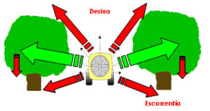
Figure 1. Distribution of sprayed plant protection product. Drift and run-off.
There are three factors that influence the effectiveness of a treatment to control a pest: the biocidal capacity of the product, the timing of the treatment and the correct selection and regulation of the machinery, which is responsible for providing the right flow rate and droplet size for the treatment.
The biocidal capacity of plant protection products must be demonstrated at the time of registration. All the information on which products are registered for citrus for the different pests can be found on the website of the Ministry of Agriculture and Fisheries, Food and Environment (MAPAMA) (http://www.mapama.gob.es/es/agricultura/temas/sanidad-vegetal/productos-fitosanitarios/registro/menu.asp).
Assuming that a product with the appropriate biocidal capacity is used, the timing of its application has a great influence on its efficacy, as this depends greatly on the stage of development of the living forms of the pest population and the meteorological conditions. Regarding the evolution of the pest, as individuals develop, their sensitivity to the action of plant protection products varies, as they may develop shields, colonies, cobwebs or excrete substances that protect them and prevent or reduce the possibility of the product reaching their sensitive organs. For this reason, it is recommended to carry out treatments when there is a majority of individuals in the most product-sensitive stage .
As regards weather conditions, there are favourable ranges of temperature, relative humidity and wind speed that increase the persistence of the product or favour its arrival at the target. Thus, as a general rule, it is recommended to carry out treatments at temperatures below 25°C, relative humidity above 50% and practically no wind (winds less than 3 m/s). In conditions of high temperature or low relative humidity, the spray droplets are easily evaporated, which causes a decrease in their size and favours drift, even leading to their disappearance before they reach the target. Likewise, if the weather conditions cause rapid evaporation of the product deposited on the tree, its biocidal effect may be reduced, as the time of exposure of the pest to the product decreases.
Excessive wind increases drift, as do the vertical currents that occur when the air that is in contact with the ground warms and rises. These situations of atmospheric instability occur, for example, during midday on summer days, especially in areas where coastal breezes prevail.
Generally, professionals in the sector have a lot of information on the different crop protection products available on the market. However, there is a lack of information on the correct way to distribute them and the effectiveness of the treatments depends a lot on the way they are applied. Hence the importance of the correct use and maintenance of machinery.
As previously mentioned, for the product to be correctly sprayed, the machine must provide an adequate droplet size, which depends on the mode of action of the product and the pest to be controlled. Depending on their mode of action, plant protection products are classified as follows:
Contact: these are those that penetrate the pests when they come into contact with them.
Inhalation: they produce vapours that affect the pest when they are breathed in.
Ingestion: these are products that are toxic when ingested by pests.
Suffocation: they act physically, blocking their airways. A typical example is mineral oils, which do not act by contact but by covering the pest's respiratory tract.
Taking into account the mode of action of the products and the type of pest to be combated, phytosanitary treatments can also be classified according to their mode of distribution, distinguishing between:
- Covering treatments. These are the most commonly used in citriculture, since most pests are fixed to the plant organs or have reduced mobility. In these treatments, a large area of the tree is intended to be covered in order to increase the probability of reaching the pest. This is achieved by using large spray volume rates. However, in citrus treatments it is very difficult to achieve a homogeneous coverage due to the globular shape and dense foliage of the trees, hence the importance of adjusting the machines correctly.
- Bait treatments: In these treatments, the objective is to attract the insect to the insecticide, so their efficacy does not depend so much on the coverage. They are used in the case of mobile pests, such as the Mediterranean fruit fly. This involves spraying the product along with an attractant to form small deposits on the vegetation, which act as a bait. Generally speaking, it is not necessary to apply them to the canopy of all of the trees, nor to penetrate into the interior of the canopy. Bait treatments normally require droplets that are large in size (1-4 mm in diameter) to increase the residence time of the product on the tree and high spray volume rates are not required.
- Systemic treatments: these are distributed throughout the tree because they are carried by the sap. They do not require large coverage.
The size and quantity of the droplets in which the product is distributed depends on the type of nozzle, its outlet section and the pressure at which the mixture reaches the nozzle, as well as the intrinsic characteristics of the liquid to be sprayed. In a nozzle, the higher the pressure, the more liquid that is distributed and the finer the droplets. Therefore, it is essential to select the nozzles properly and control the pressure to produce an adequate droplet size.
From the point of view of the adjustment of the sprayer, a homogeneous treatment is achieved by the appropriate selection of:
- the working pressure and the type of nozzle with which the treatment is carried out, which must produce the desired droplet size.
- the forward speed, which varies both the coverage achieved and the amount of product deposited per unit area
- in the case of air-assisted sprayers, theair flow rate and speed of the air to reach the areas to be treated and to shake the leaves so that the product is spread over the entire target area.
The equipment used to carry out phytosanitary treatments against citrus pests are hydraulic sprayers, with and without air assistance. The equipment used is listed below:
Knapsack sprayer
These are devices with small capacity plastic tanks, which are worn on the back like a knapsack, hence their name (Figure 2). Depending on their energy source, there are two types of knapsacks: manual and electric.
 Figure 2. Knapsack sprayer.
In the case of manual versions, the pressure is continuously generated by the operator, who operates a small pump with a lever. As a rule, this lever should be easily mounted to the right or left of the operator. The tank has an air chamber which acts as a pressure accumulator. This chamber should have a volume of at least ten times the displacement of the pump, in order to achieve an output of liquid at approximately constant pressure without the need for continuous rhythmic pumping. The pumps can have a piston (up to 6 bar) or diaphragm (up to 4 bar).
In electric knapsacks, the pressure is generated by an electric pump, usually a diaphragm pump, powered by a battery. In both types of knapsack, the product is distributed by means of a lance, at the end of which there is a nozzle or several nozzles attached to a small bar.
A wide range of knapsacks can be found on the market, but all of them must comply with the ISO 19932-1:2006 and ISO 19932-2:2006 standards, regarding the safety, mechanical resistance and water-tightness tests they must pass. When acquiring them, it should be taken into account that they must have sufficient pumping capacity and must have systems that prevent the operator from accidentally coming into contact with the liquid. It is very important that they have sufficient mechanical strength to withstand prolonged use, especially to avoid tank rupture or leakage of the equipment.
It is recommended that the tank should not exceed a maximum capacity of 15 litres and should not leak even when lying on the floor. It should have a sufficiently wide mouth to facilitate filling with a bucket and have a device at the bottom to facilitate emptying when an application is finished.
Hose and “gun” hydraulic equipment
They involve an intermediate degree of mechanisation, since, although they generate the pressure of the liquid with hardly any operator intervention, the distribution of the liquid over the vegetation is carried out manually (Figure 3). This equipment has large-capacity tanks (500-2000L), driven or suspended from a tractor.
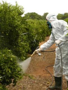 Figure 3. Hydraulic gun sprayer.
They are also called jet sprayers because the energy required for the spray to reach its target is mainly provided by the pressure of the liquid. The reach of the droplets produced by the nozzle depends mainly on the pressure, so high pressures (20-30 bar) are usually used to reach the inside and upper parts of the canopy.
The nozzles are placed on a manual device (gun), which is connected to the pump by means of a flexible hose, which facilitates the movement of the operator between the trees. It is recommended that the hoses are shorter than 25 m in order to be manageable and to reduce pressure losses between the pump and the nozzle. Also, their diameter should be sufficient so as not to increase pressure losses.
The spray guns have an adjustable opening and closing system that allows the opening angle of the spray jet to be modified. By varying the opening angle, the diameter of the outlet pipe of the spray liquid is modified and, therefore, the pressure, which modifies the range and size of the droplets produced. Opening angles of 25-35º are recommended.
Air-assisted hydraulic sprayers (airblast sprayers)
This is the equipment that allows the highest degree of mechanisation during application, as it only requires the tractor driver. In addition, they reduce water consumption and product losses due to run-off. By allowing treatment to be carried out in a short space of time, they ensure that it can be done at the moment when the pest is most sensitive.
On the market you can find suspended equipment up to 1000 litres, but most of the equipment currently in use is pulled along and has larger capacity tanks (1000-3000L).
They are called air-assisted hydraulic sprayers (Figure 4) or transported jet spraying because the drops produced in the nozzle are incorporated into an air stream that ensures their transport to the crop, while shaking the foliage. In addition to having a hydraulic circuit similar to that of the previous equipment, they have an air moving system formed by an axial flow fan and deflectors. The fan generates the air flow and the deflectors guide it in the desired way, making it pass around the nozzles and with the necessary turbulence to move the leaves of the canopy.
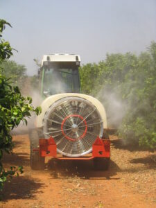
Figure 4. Air-assisted hydraulic sprayer
Most fans are equipped with a gearbox that allows two gear ratios between the tractor power take-off (PTO) and the fan shaft, so they can produce two airflow rates. In general, the lower flow rate is recommended for treatments directed towards the outside of the canopy or when working with small or very sparse trees. The higher flow rate is used when the product is required to penetrate the vegetation or reach the trunks, in medium to large trees with normal to dense vegetation.
A clutch is attached to the fan shaft to interrupt the rotation of the propeller without having to disconnect the PTO and to protect it from possible snagging.
The quality of the equipment that generates the airflow is decisive for good treatment. The equipment must provide the same airflow rate on both sides of the machine, so that the trees are treated homogeneously on both sides. In addition, the air must be blown at the right speed and in the right direction to move the leaves, but without going too far beyond the top of the tree. To achieve this, manufacturers incorporate different types of deflectors, both at the fan inlet (to ensure that the flow is distributed equally on both sides) and at the fan outlet (to produce turbulence directed towards the tree). Some units have vertical deflectors at the fan outlet to reduce drift losses.
The pressure of the hydraulic circuit should not be high, as in the case of spray gun equipment, as it only has the task of forming the droplets, not transporting them. Therefore, around 7-15 bar is recommended. Higher pressures lead to higher fuel consumption, wear on pumps and hydraulic circuitry, and result in droplets that are too small that lead to evaporation and drift.
The recommended forward speed during phytosanitary treatments in citrus is between 1 and 3 km/h. Lower speeds are used when the product is required to penetrate the vegetation, and higher speeds are used when treatments are directed to the outside of the canopy.
The spray volume rate to be applied depends on the pest, the product and the vegetation on the orchard. In order to help the farmer to decide what spray volume rate to use in a treatment, we have developed the tool "CitrusVol" which can be found in the final corresponding section of this webpage.
This section describes in detail the most important elements of the hydraulic circuit and, in the case of air-assisted equipment, the air flow generation system. All the hydraulic circuits of the machines for the distribution of treatments consist of: the tank, the pump, the pressure gauge, the nozzles and the filters.
Tank
The tank is the place where the mixture to be sprayed is prepared and kept. Two materials are currently used in the market to make these tanks: fibreglass (polyester) or polyethylene. Polyester tanks are more expensive and difficult to clean on the inside, but can be easily repaired in case of breakage. Polyethylene tanks are cheaper and easier to clean but are more fragile and difficult to repair.
Many plant protection products are quite insoluble, or, as with mineral oils, must be kept in an emulsion that is relatively unstable. Therefore, tanks must have a good agitation system. Although there is still some equipment with mechanical (paddle) agitation systems (Figure 5), hydraulic systems (Figure 6) are usually more efficient and consume less energy. In these systems, part of the flow supplied by the pump is diverted into the tank and, thanks to a nozzle, is injected into the mixture and removes the liquid from the tank.
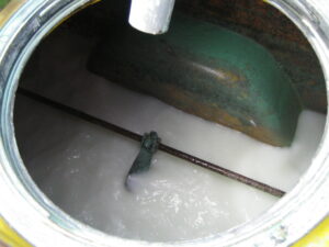
Figure 5. Mechanical agitator
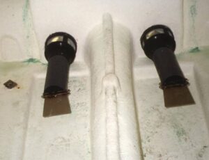
Figure 6. Hydraulic agitator
One or more tanks for rinsing the equipment, separate from the 'clean water' tank for the operator, with a capacity of at least one tenth of the tank volume, are recommended. It is also recommended that they have devices for cleaning plant protection product cans, with the possibility of recovering and transferring the cleaning water to the tank.
The tank’s sealing is key to a safe and environmentally friendly application and must be checked regularly.
Pump
The pump is one of the most important elements of the equipment. It provides the necessary pressure to the hydraulic circuit. There are currently two types of pumps on the market: piston pumps (Figure 7) and piston-diaphragm pumps (Figure 8). No data is available to indicate which one performs best. In both cases, the pumps can be accompanied by shock absorbers, whose mission is to maintain the pressure constant and avoid the ups and downs in the pressure that produce the strokes.
The pump must be checked periodically for leak tightness, proper lubrication and to make sure the pistons or diaphragms are in good condition.
Figure 7. Piston pump
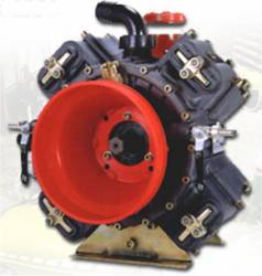
Figure 8. Piston-diaphragm pump
Pressure gauge
A very important element in the equipment is the pressure gauge (Figure 9). It is practically the only indicator that the applicator has to know whether the task is being carried out correctly. We must not forget that pressure influences the flow rate through the nozzles and the size of the droplets they produce. Therefore, the pressure is, along with the forward speed of the equipment, a determining factor in the effectiveness of the treatment.
One has to bear in mind that the pressure at the pump outlet, which is where the pressure gauge is usually located, is not the same as at the nozzles, as pressure losses occur in the pipes/tubing. It is therefore recommended to be aware of these losses and to take them into account when carrying out the treatments.
Figure 9. Pressure gauge.
The nozzles are the active elements of the equipment (Figure 10). Their task is to divide the flow of spray into small portions. The nozzles most commonly used today to distribute insecticides are turbulence nozzles, either hollow cone or full cone nozzles. These nozzles consist of two parts: the diffuser and the core, both parts are either separate or integrated in a plastic body.
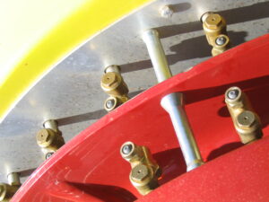
Figure 10. Nozzles and anti-drip system.
What should be remembered is that the flow rate through a nozzle is approximately proportional to the square of the orifice diameter and the square root of the pressure. Therefore:
- to increase the flow rate considerably, it is recommended to replace the nozzle with a larger orifice instead of increasing the pressure.
- If the nozzle wears out quickly, this means there’s an increase in the flow rate provided by the nozzle: a nozzle that provides more than 10% of the nominal flow rate should be replaced immediately.
- if the nozzle becomes clogged, there is a noticeable reduction in the flow rate provided by the nozzle. To clean it, it is recommended to use clean water and a soft brush. Never blow with your mouth (danger of poisoning) and never use a wire (it will damage the nozzle) to unclog the nozzle.
- ceramic: They are highly resistant to wear, but produce droplets with a very wide droplet size distribution.
Filtres
The purpose of the filters is to keep the equipment in good working order. They must protect the pump (Figure 11) and the nozzles, preventing the entry of particles that could cause abrasion of the fixed or moving parts or clogging of the nozzles (Figure 12).
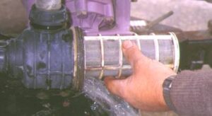
Figure 11. Filter at the pump inlet
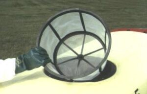 Figure 12. Filter at the tank inlet
Fan
As mentioned above, air-assisted equipment is equipped with an axial fan that causes the leaves to move and transports the droplets to their final destination.
It is very important to point out that it is the most energy-consuming element. For three reasons: the quality of the droplet transport, the generation of movement in the leaves to be able to treat them properly and the high energy consumption, the design of the fan is decisive in the performance of the equipment.
The air outlet must be symmetrical on both sides of the unit. The fan guards must be kept clean of leaves and dirt, in order not to reduce the efficiency of the fan.
Cleaning and maintenance are aimed at guaranteeing the safety and health of people, reducing contamination and ensuring proper distribution of the plant protection product.
As already mentioned, the means used for the application of plant protection products determine to a large extent the effectiveness of the treatment. When equipment is not kept in proper working order, it is not possible to control the parameters that affect the effectiveness of the treatment. In addition, poorly regulated equipment or equipment with excessive wear has a higher polluting potential and increases the risks of toxicity for the farmer.
The European Directives on the safety of machinery (98/37/EC) and on machinery for pesticide application (2009/127/EC) require the purchaser to be provided with an instruction manual in the language of the country in which the equipment is sold. This document must contain the maintenance instructions for the equipment and must be required from the seller.
Equipment maintenance is an integral part of the application work. If done properly, it maintains the quality of the treatments and extends the lifetime of the machines. The most important consequences of lack of maintenance are listed in Table 3.
| ELEMENT | CONSEQUENCES |
| Dirty, broken of missing filters | Pressure loss |
| Wear of other elements: pump, nozzles and valves. | |
| Illegible or damaged pressure gauge | Wrong dosage |
| Inadequate product distribution | |
| Pump | Wrong dosification |
| Worn nozzles | Irregular dosification |
| Increased run-off | |
| Faulty fan | Non-homogeneous product distribution |
| Drift increase |
Table 3. Consequences of inadequate maintenance
New equipment start-up
Before working with a new sprayer, in order to remove the residues produced during the machining and manufacturing of the hydraulic circuit, it is recommended to:
- remove the drain plug and rinse the tank with water.
- replace the plug and fill the tank up to 20% of its capacity.
- operate the sprayer and open the dispensor to empty all lines, removing a nozzle (or plug) at the end of each line that has an independent supply.
- dismantle, clean and reassemble all filters and nozzles.
END-OF-DAY MAINTENANCE
If after treatment, any mixture that hasn’t been distributed remains in the tank, the following rules must be followed:
- Do not discharge leftovers into a river or in the vicinity of any water point.
- Empty and rinse the equipment with caution in places as far away as possible from drinking water points. Never leave mixture in the tank without continuous agitation.
- Rinse the tank inside and out with a hose.
- Fill the tank with clean water and the corresponding additives according to the type of product used in the treatment:
- Oily products: water with liquid detergent, and finish off by rinsing with pure water.
- Hormonal herbicides: 1-3% ammonia solution diluted to 1 litre of ammonia solution per 100 litres of water and several rinses. Activated carbon at 100 grams per 100 litres for 12 hours. Important: use appropriate Equipment of Personal Protection when diluting and rinsing the tank.
- Copper residues: acetic acid (1 litre vinegar per 100 litres water). Wait 2 hours after rinsing.
- Sodium chlorate and synthetic organic fungicides: any residues must be removed from inside and outside the tank to avoid the risk of fire.
- Operate the agitation device so that water flows through all the pipes to the nozzles.
- Check the nozzles and clean or replace any that are faulty.
- Check filters, remove and clean any clogged filters.
- Check greasing points.
- Check oil levels in pump sump. Add or change if necessary.
- Check tyres.
- Keep fan guard clear of leaves and foreign matter.
- If there is a risk of frost, completely drain the pipes and pump, or use an anti-freeze solution.
AT THE END OF THE SEASON
Before storing the sprayers for a long period of time, the following operations must be carried out:
- Thorough cleaning.
- Drain pumps and lines.
- Check oil level in pump sump.
- Grease all moving mechanical parts.
- Check tyre inflation pressure.
- Depressurise the pressure regulator valve so that its operating spring is at rest.
- Protect any areas that have been rubbed or worn with paint to prevent them from rusting.
- If possible, leave the machine off the ground in a dry place.
Inspection of sprayers
Royal Decree 1311/2012 published in the Official State Gazette in September 2012, which establishes the framework for action to achieve a sustainable use of plant protection products in Spain, establishes that application equipment must be in perfect working and maintenance conditions and correctly calibrated at all times, to guarantee accurate dosages, improve the quality of applications and prevent the risks associated with them.
To this end, plant protection product application equipment must undergo a technical inspection on a regular basis. This inspection is regulated by RD 1702/2011. This specifies which equipment is subject to inspection. These are:
- Mobile plant protection product application equipment, used in primary production, agriculture and forestry, as well as equipment used for other professional uses, and corresponding to some of the following types of machinery:
- Hydraulic sprayers (boom or spray gun)
- Hydro-pneumatic sprayers
- Pneumatic sprayers
- Centrifugal sprayers
- Dusters
- Application equipment mounted on board aircraft.
- Equipment installed inside greenhouses or other enclosed premises, such as fruit and vegetable plants.
Knapsack sprayers and hand-pulled sprayers (wheelbarrows) with a tank of less than 100 litres are excluded.
It is important to point out that in order for equipment to be inspected, it must be registered in the Official Register of Agricultural Machinery, the R.O.M.A., which exists in the corresponding Territorial Directorate in each province.
The inspection of the equipment is carried out by the ITEAFs (Technical Inspection Stations for Plant protection Application Equipment). The owner of the equipment may choose the ITEAF, all of them having a mobile unit that will allow them to travel and carry out the inspections in the different farms, cooperatives, agricultural companies, etc., located in the corresponding autonomous community.
During the inspection, compliance with the established regulatory requirements is verified and basically includes the following checks:
- Checking the correct state of the pressure gauge.
- Measurement of the air outlet flow of the fan in the airblast sprayers.
- Measurement of the sound level (noise) endured by the worker.
- Checking the pressure loss between the regulator and the nozzles.
- Measurement of the liquid outlet flow rate at all nozzles.
- Checking the nozzles’ level of wear.
- Checking the condition of filters, valves and piping.
- Checking the general condition of the pump.
- Observations on the general condition, maintenance and upkeep of the equipment.
- Checking the correct state of the safety measures and devices.
As a result of the inspection, the user receives a technical report on the state of the equipment at the time of the test, as well as recommendations on how to improve its performance.
More information can be found by clicking the following link:
Inspection manual for plant protection application equipment in use.
The air-assisted hydraulic sprayer is the most complex equipment and its correct use depends mainly on its adjustment. Adjustment operations, often incorrectly called equipment calibration, consist of a set of calculations to decide:
- The nozzles (type and number) to be used for treatment
- The pressure
- Tractor forward speed
1. Definitions
Often different words are used to express the amount of plant protection product to be distributed in a treatment and sometimes the same word, depending on who uses it, is given different meanings. Both situations lead to a great deal of confusion among operators and technicians and make it difficult to compare the results of treatments. For this reason, it is important to clarify the terms and always use them in the same way. In this section we define the following:
- Spray volume rate: quantity of spray liquid applied per unit area (L/ha).
- Dose: quantity of plant protection product that is distributed per unit area of ground (L/ha or kg/ha) or unit volume of vegetation (L/m3 vegetation).
- Concentration: The amount of plant protection product in the mixture (usually expressed as a percentage, as cm³/hl, etc.). This concentration is often confused with the dose, as the word dose appears on the labels of plant protection products.
- From these three definitions it can be deduced that DOSE = SPRAY VOLUME RATE x CONCENTRATION x constant. Where the constant is a number to correct the units in which the concentration and spray volume rate are expressed.
For example, a mixture, which is distributed at a rate of 2000 L/ha of a product mixed at 1%, generates an application dose of:
DOSE (cm3 of product/ha) = 2000 l of mixture/ha x 1 cm3 of product/ 100 cm³ of mixture x 1000 cm3 /L = 20000 cm³ of product/ha = 20L of product/ha.
How to adjust a tractor-driven sprayer.
Once the spray volume rate has been determined, the following steps must be taken to adjust a sprayer:
- Select the engine speed (revolutions) of the tractor.
- Select the forward speed of the tractor.
- Determine the total instantaneous flow rate to be delivered by the equipment (L/min).
- Select the nozzles and working pressure. Check the flow rates.
- Calculate the quantity of plant protection product and water to be added to the tank.
Practical example
It is recommended to carry out an insecticide treatment against whiteflies with a spray volume rate of approximately 1750 L/ha. As this is a treatment against an external pest, the forward speed of the equipment should be between 2-3 km/h. The treatment will be carried out in an orchard planted at 6 x 4 m. The treatment will be carried out with an airblast sprayer with a tank whose capacity is 1500L and has 16 nozzles.
Let’s suppose we want to use a product with the following characteristics:
Active substance: BUPROFEZIN 25% [WP] w/w
- Presentation: EC - Emulsifiable concentrate
- Label dose (recommended concentration): 0.04-0.08 (%)
2. Select the speed (revolutions) of the power take-off and engine.
Normally, the manufacturer of the sprayer recommends a PTO speed that he considers to be optimal for the operation of the sprayer. At this PTO speed, the drive shafts, pump and fan rotate at an optimum speed which makes them more efficient (producing sufficient pressure and air quantity respectively, with less consumption and wear).
Today's manufacturers generally recommend a PTO speed of between 480 and 540 revolutions per minute (rpm). In the example we will assume that the manufacturer recommends 540 rpm. Once the power take-off (PTO) speed has been set, it remains to determine what the corresponding tractor engine speed should be.
The speed of the PTO and the engine are related by the so-called gear ratio, which is defined as follows
Gear ratio= Engine speed / PTO speed [3].
Or put in another way:
Engine speed = gear ratio x PTO speed [4].
If we have a tachometer, we can measure both rotational speeds. For example, let’s suppose that when the tractor engine turns at 1700 rpm, we measured with the tachometer that the speed of the PTO was equal to 452 rpm. Then, the gear ratio is:
Gear ratio = 1700 / 452 = 3,78
The speed of the PTO we want is 540 rpm, therefore, the engine speed we need to work at is:
540 x 3.78 = 2041 rpm
However, we often do not have a tachometer. In that case we can:
- Refer to the technical data book of the tractor and find the gear ratio between engine and PTO speed.
- On many tractors, the control panel indicates not only the engine speed, but also the PTO speed. Many modern tractors have an electronic panel which indicates this, but older tractors also have a mechanical needle system which allows this to be known.
- On some tractors, the engine speed which produces 540 rpm at the power take-off is marked on the panel.
3. Select the forward speed of the tractor.
When the tractor is working at very low speed, as is the case when applying phytosanitary treatments in citrus, the forward speed indicated by the control panel is unreliable, even if the panel is electronic. For this reason, it is advisable to make more accurate measurements of this forward speed using a simple procedure, consisting of making the tractor travel a known distance at the speed calculated in the previous section and measuring the time taken to cover it. These measurements are made in each of the tractor's lowest gears and need not be repeated as long as the wheel size is not changed. To obtain the speed of the tractor in kilometres per hour, the following calculation is made:
Speed (km/h) = Distance travelled (m) / Time taken (s) x 3.6
Let us assume that a test is carried out with the above tractor, which has four low speeds and four high speeds. The tractor is set to 2041 rpm and the time taken to travel a distance of 100 m in a straight line is timed. The following times are obtained:
| TRACTOR’S GEAR | TIME (s) |
| 1st Low | 234.8 |
| 2nd Low | 163.9 |
| 3rd Low | 138.7 |
| 4th Low | 109.2 |
| 1st High | 76.2 |
| 2nd High | 65.5 |
The ground speed in kilometres per hour is calculated using the above formula and results:
1st low at Speed (km/h) = 100 (m) / 234.8 (s) x 3.6 = 1.5 km / h
2nd low at 2.1 km/h
3rd low at 2.5 km/h
4th low at 3.2 km/h
Therefore, for the treatment we choose 2nd low gear, which produces a tractor speed of 2.1 km/h when the tractor engine is running at 2041 rpm.4. Determine the total flow rate to be delivered by the equipment (L/min).
The flow rate to be delivered by the equipment is calculated with the following formula:
Total flow rate (L/min) = (Speed (Km/h) x row spacing (m) x Spray volume (L/ha)) / 600
Bearing in mind that the row spacing is 6m, we have to:
Total flow (L/min) = 2.1 Km/h x 6 m x 1750 L/ha / 600 = 36.8 L/ min.
5. Select nozzles and working pressure. Check the flow rates.
The equipment has 16 nozzles, however, depending on the vegetation, it is possible that not all of them will be used. To find out the number of nozzles to be used, spray the plot with water, stand behind the equipment and close or orientate the nozzles that do not direct the jet towards the vegetation.
In this case, we are going to assume that the vegetation is thick and that all 16 nozzles will be used. Therefore, the flow rate to be delivered by each nozzle is as follows:
Flow rate per nozzle (L/min) = 36.8 L /min / 16 nozzles = 2.3 L /min.
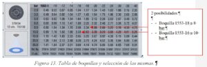
Figure 12 shows a nozzle table and indicates the possible nozzles to be used within the recommended pressure range (7-12 bar). 2 possibilities exist:
- Nozzle 1553-18 at 8 bar.
- Nozzle 1553-16 at 10 bar.
We decided to select the 1553-16 and the working pressure will be 10 bar.
However, it may be desirable to distribute the flow rate of the equipment proportionally to the vegetation. Let assume that there is more vegetation at the top of the trees, as shown in Figure 13.
Figure 13.- Percentage distribution of the mixture in the vegetation.
In this case we will proceed as follows. The flow rate to be delivered by the nozzles in the upper half is 60% of the total, i.e. 36.8 x 0.6 = 22.1 L/min.If we put all the nozzles equally in the upper half, each nozzle should deliver
22.1 / 8 = 2.7 L/min
The 1553-20 nozzle at 8 bar delivers 2.68 L/min.
The flow rate to be provided by the lower half of the machine is
36.8 x 0.4 = 14.7 L/min
Each nozzle should then deliver 14.7 / 8 = 1.8 L/min, which leads to the choice, using the previously selected pressure (8 bar), of the 1553-14 nozzle, which delivers 1.7 L/min.
In this way, with two types of nozzles, the flow rate can be divided so that more spray is directed to the top of the tree.
6. Flow rate verification:
In general, the theoretical flow rates are not exactly the same as those provided by the nozzles, so it is advisable to recalculate the spray volume rate actually applied.
To do this, using a watch and a measuring cylinder or bucket, the flow rates provided by the nozzles are measured when the pressure gauge of the equipment indicates the pressure at which the treatment will be carried out. Once the flow rate provided by the equipment (Q (L/min)) has been calculated, the spray volume rate applied is calculated using the formula:
Spray volume rate (L/ha) = [Q (L/min) * 600] / [v (Km/h) * A (m)].
7. Calculate the amount of plant protection product and water to be added to the tank.
As the recommended concentration of the product on the label is 0.04-0.08%, we assume that we want to use 0.06%. The amount of product to be added is:
1500 L of water * 0.06 L of product / 100 L water = 0.9 L product.
CHECKING FOR CORRECT APPLICATION
Once the equipment has been adjusted, it is important to check that the desired coverage is achieved on the vegetation. To do this, an area of the plot is sprayed with water and two checks are made:
1-Look the airblast sprayer from the rear part and check that all flow is directed to the vegetation.
2-Water-sensitive papers (yellow papers that change to blue when in contact with liquids) are placed on the vegetation and the coverage produced is observed.